Majority Vote

The purpose of the circuit we designed was to create a voting system. All of the directors must agree on the decision or the vote would be a no, and if there was a tie, the presidents vote would decide. We were constrained to two chips so we had to wire intricately.
Problem Conception
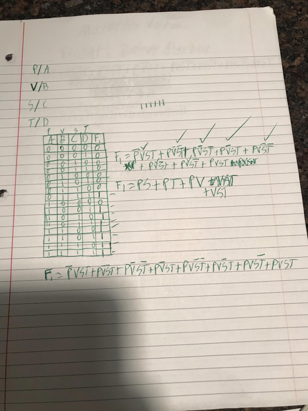
The truth tables purpose is to reflect all of the possible outcomes that could happen with each input from the voter. We had 16 rows because we had 4 inputs with each of the 4 voters. 2^4=16. In a tie, you would have two zeros and two ones in a row. This means two members voted yes and two members voted no. The tie ends up being a yes or no depending what the presidents vote happened to be, if his was one then the vote will come to a one and vice-versa. My expression is in SOP form. The are 8 minterms that you can make from the table and SOP form makes it simpler to read and visualize those in my opinion.
Unsimplified Circuit
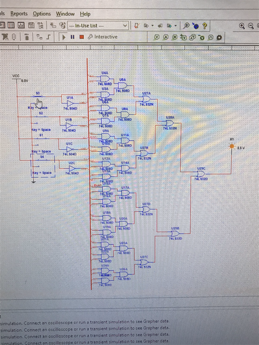
My circuit I created is ran off of a bus, this cleans the circuit up by keeping it neat and organized, and facilitates making the actual circuit sim. I used (3): AND, OR, and INVERTER gates. The AND gate multiplied two terms, the OR adds two terms, and the INVERTER changes the status from for example not a to a or vice versa. I used 4 inverters, 24 and gates, and 7 or gates. I would need a total of 9 chips to bread board the circuit.
Boolean Algebra Simplification
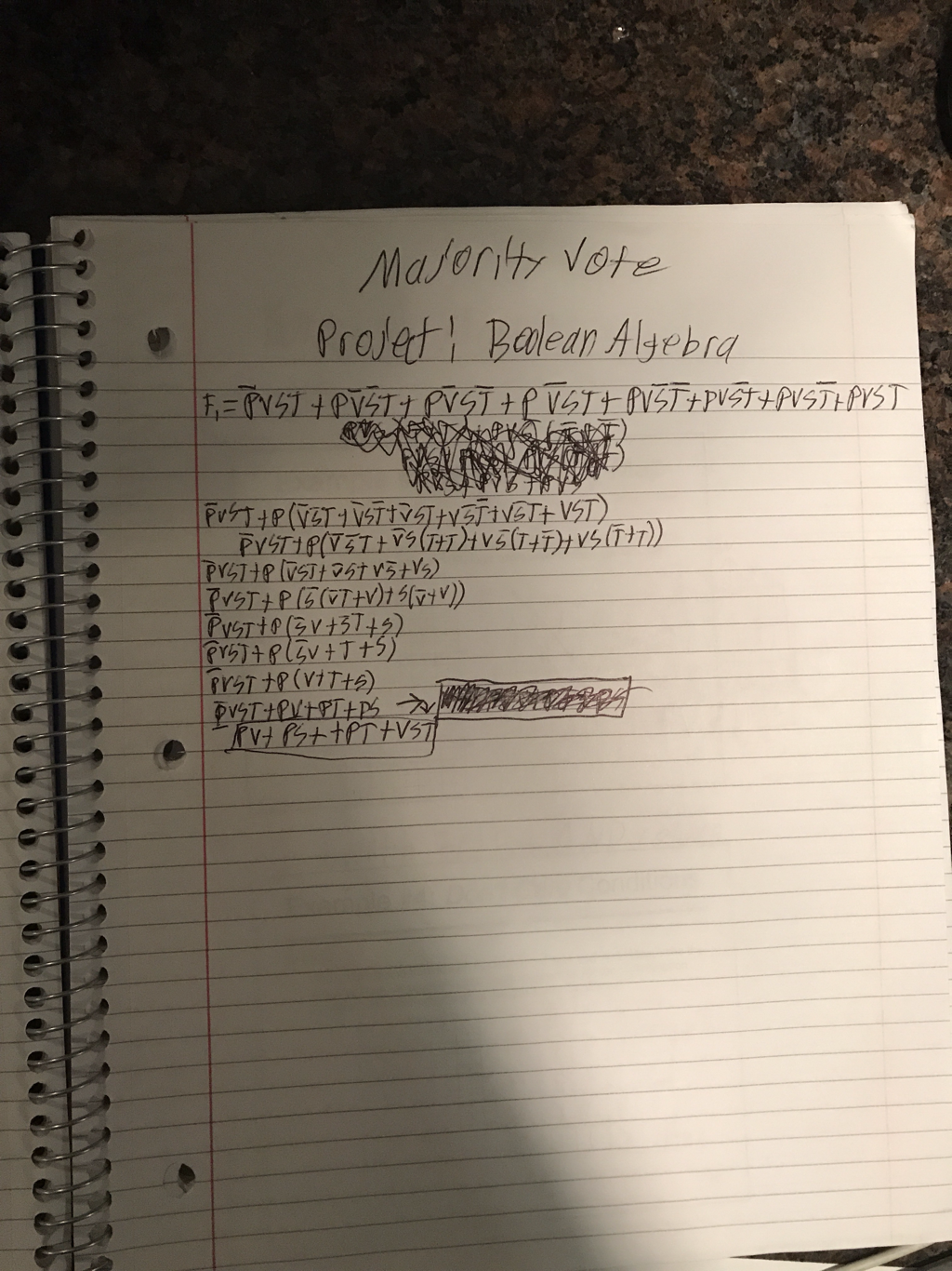
Boolean algebra was used to simplify our unsimplified expression. This will make wiring easier and make the overall circuit more efficient instead of using all 35 gates. 8 minterms became 4 minterms which will be much easier to physically make.
Simplified Circuit
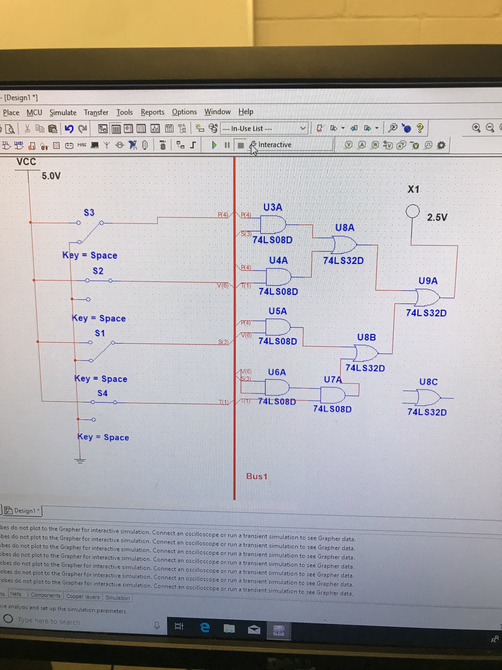
Above is my simplified circuit. I built it in bus form because it offers a cleaner way to make all of the necessary connections without getting confused hardwiring everything together. If I were to construct this in real life, I would need to place a resistor before the LED so I don’t burn it out with all the power running through the circuit. There is a total of 8 gates being used, so I need 2 and chips and 1 or chip. The simplified circuit contained far less gates and chips than the unsimplified. This is important because in real life, you wanna build your product with as little work and money as possible. Building the unsimplified circuit would waste more time and money compared to the simplified which would be less and more efficient.
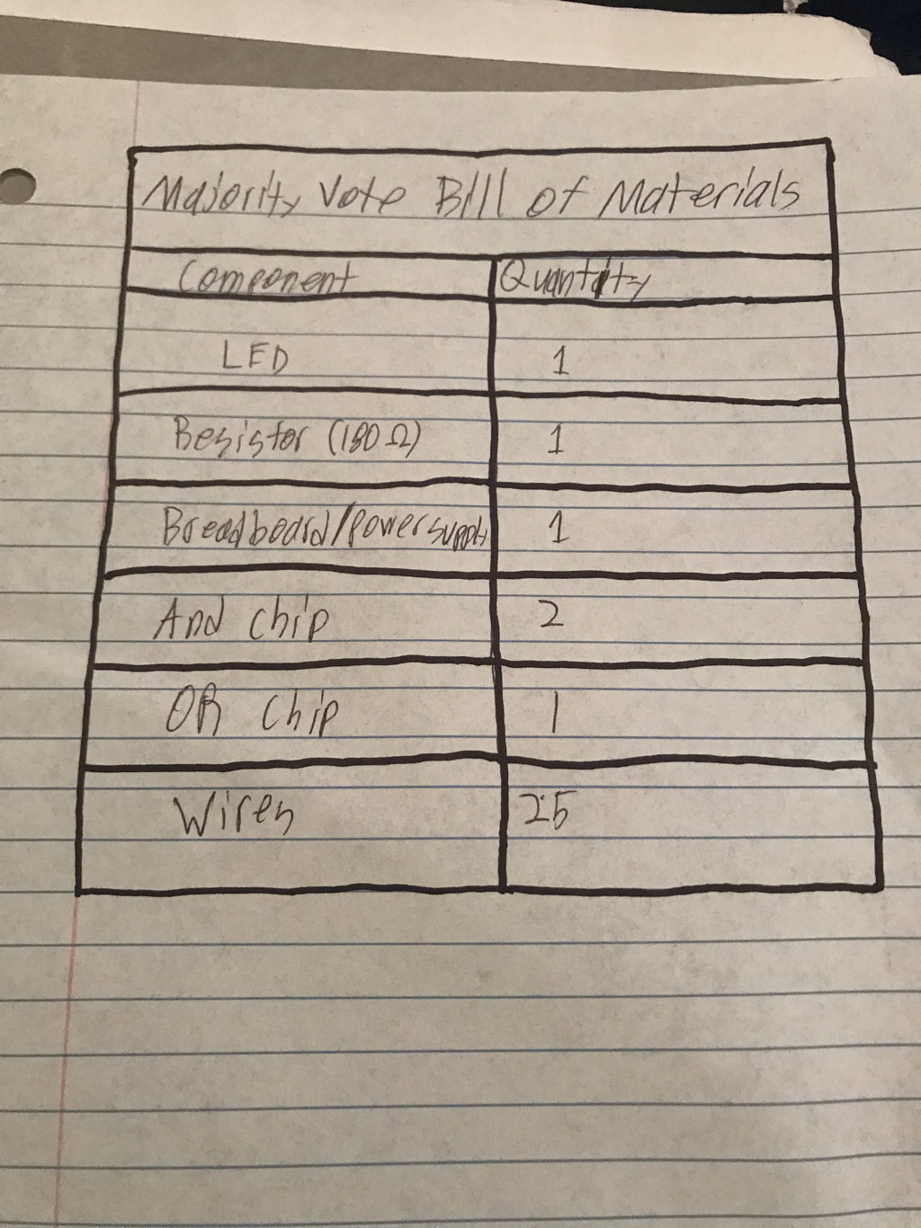
“Bill of Materials”
Below is the list of materials used to build the circuit. This describes how many of what components and parts we will need.
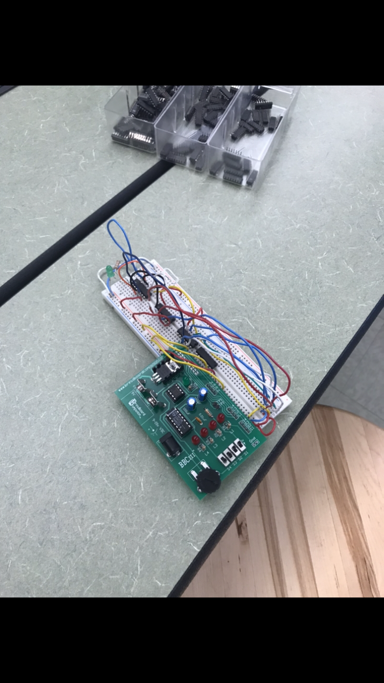
Bread Boarding
Looking back at this experience, it seemed pretty stressful with it being fairly new to me and worrying so much about placing the right wire in the right spot. I didn’t make too many mistakes, most of them were wrong wires where they shouldn’t be. Shown below are pictures towards the end of my construction process. A troubleshooting method I used is to literally retrace each wire from the input to make sure it went to the right spot on the chips. Another mistake I make at one point was not wiring the led and resistor together properly so my circuit was correct, but that wasn’t lighting up.


Conclusion
One take away from this project at least for me is to not give up. Yes, it was stressful but by being persistent and not giving up i was able to build a functional circuit. This project shows our knowledge of basic logic, bread boarding, and Boolean algebra. This project was very neat to me because I really got to see it transform through the design process from thoughts on a paper, to a computer simulator, to a real functional circuit. Boolean algebra was very much useful because instead of having to breadboard that entire unsimplified logic expression, we only had to build the much smaller and simplified one.
