Copy-Jam Project
Beginning
For this project, we were to create an electrical circuit wired into a device that would simulate a jam in a printer or copy machine. Some constraints included the machine beeping when 2 or more phototransistors were blocked, and being able to stop the beeping by toggling a switch on the breadboard.
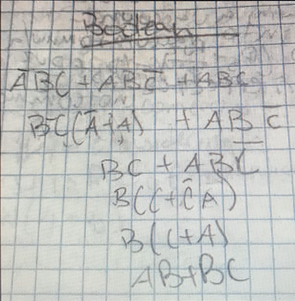
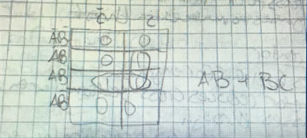
Below are is the truth table, Boolean algebra, k-map, and simplified expression.

Circuits
Reading the external wiring diagram wasn’t as bad as Aidan as I thought. It was different than we were used to, but as long as we payed attention as to what went where, it wasn’t too hard. Implementing the flip-flop also was not as hard as we thought, all it was was plugging the correct wires into their respective spots on multisim and ensuring a solid connection on the actual breadboard. The resistors were used to limit power through the chips and other components so they wouldn’t burn out. The purpose of the combinational logic circuit is to let the buzzer know when to sound. It prepares the machine for a “copy jam” by making the machine act a certain way (buzzer activated) when this condition is true. The flip flop is what digitally detects the jam and what tells the logic to run. When it tells the logic to run, the buzzer sounds and will remain sounding until the manual “clear” switch is activated to reset the circuit.
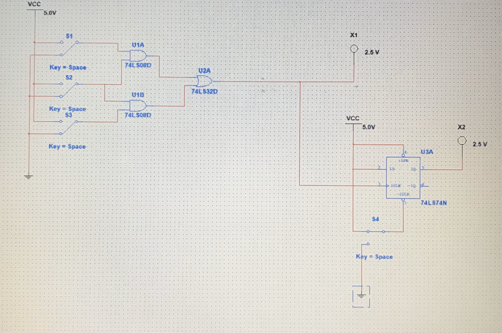
Below is a picture of our multisim circuit.
Conclusion
This project i enjoyed for it being different than our other projects. It was more hands on with the construction of the machine which was fun to build, we implemented a flip-flop component, and we implemented an external power supply for the machine lights. Through this project, I learned several things. My breadboarding skills improved, my multisim skills improved, and I gained more of an understanding of the flip-flop component.
