Project Overview
The purpose of this project was for use to show our knowledge of basic electric circuits, specifically our knowledge on using certain gates on chips to display our birthday on a 7-segment display. Overall, there weren’t many constraints but the one thing we had to do was base our circuit off of a common cathode type display.
Truth Table
In the upper-left portion of the above picture is my truth table, based off of my birthday in MM/DD/YY format. Written in that table is the binary codes for what will determine the actual input for the display.
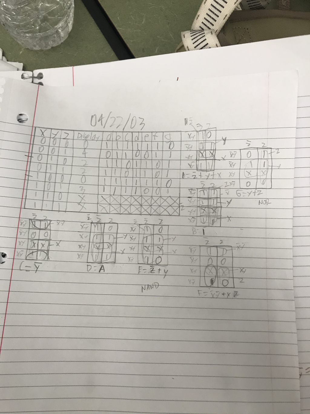
On the table, the X,Y, and Z columns represent the switches and the different positions each one with be selected to. Columns under A-G correspond with each of the seven segments on the display with each letter to a segment. So the column under a letter is that segment’s binary code.
K-Maps/Simplified Logic
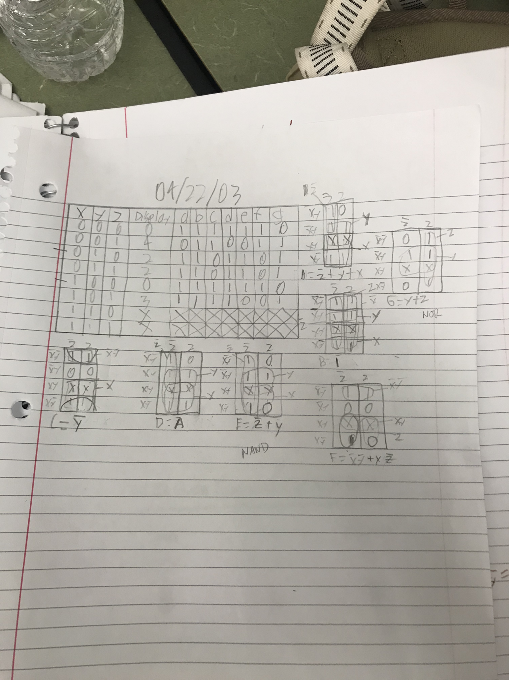
K-mapping is a way to simplify a logic expression in a considerably simple and “clean” way. It works by putting a set of binary into its own table, then grouping the 1’s and the letters that the groups have in common is the simplified logic expression. I got each of my minterms through doing like I said grouping the 1’s and finding the common letters with each. There was a new minterm through each segment of the display (A-G). We used this instead of Boolean algebra because it would’ve simply taken longer to do it that way. Also personally, I’m not too comfortable with Boolean so I felt much more confident in my simplifications using K-Maps.
MultiSim Implementation
In this project, we used MultiSim to virtually build our circuits. It allowed us to construct our gates with different chips and it gave us a plan for what we were to physically build later in the project.
My circuit above is in bus form. In total, I used 3 OR gates, 2 AND gates, 3 INVERTER gates, 3 NAND gates, and 2 NOR gates. I only needed a total of 5 physical chips to construct this circuit. We can use NAND or NOR gates in an effort to simplify the diversity of different types of chips needs by just using different combinations of one chip. My NAND and NOR segment actually ended up using more gates than basic AOI would, in total I used 3 more implementing these than I would using AOI.
In the project, we used common cathode meaning that the display needed a “1” to work. This is simpler to understand rather than using common anode and requiring a “0” to work which we could do, but would add to the confusion. Theses displays work by having a set of logic assigned to each segment and when wired through switches, can display what you want based off of what combinations of switches are being turned on and what each code is for each segment. Each different switch combination will trigger the different segments to be on or off based off of its binary code.
Bill of Materials
In the table pictured below is a type materials report. It’s a simple table recording each component and the number of them required to construct my circuit.
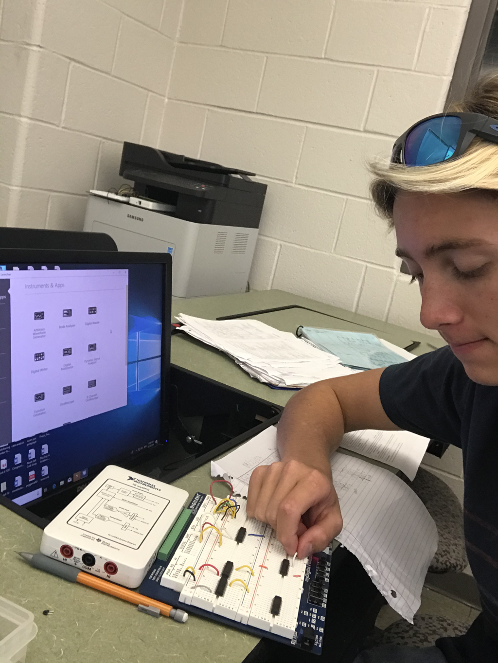
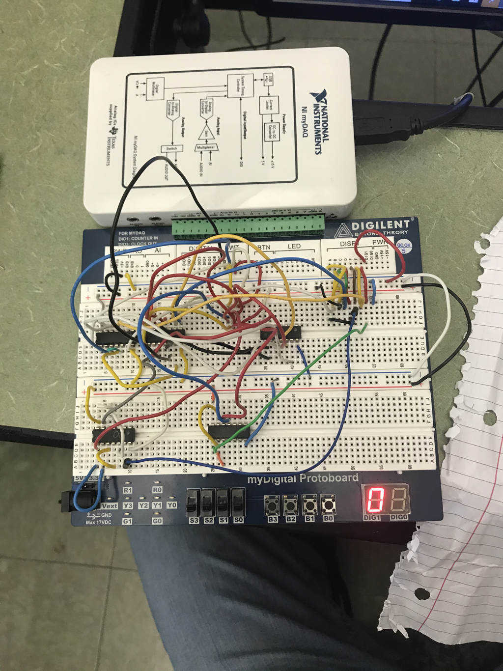
Bread-boarding
Below is my completed circuit, showing 0, the first digit of my birthday display.
Below are several pictures showing my progression over a couple of days bread-boarding this circuit.
This project was my second official bread-boarding experience. Some mistakes I made making the circuit were just being messy with my wiring as the confusion in which wires went to where lead to a faulty circuit but luckily it was found and corrected. Sometimes also, I could have placed a wire into the wrong pin on an IC chip, and that determined if it worked or not. Through this project, I immensely became more comfortable with MultiSim and breadboarding circuits.
Conclusion
Through this date of birth project, I learned more wiring skills, more computer skills, and gained a better understanding of how electrical circuits work. One thing I’d do differently next time would be to take better account for each of my wires perhaps by labeling them with tape so I remember where they go or what they’re from. I genuinely liked this project. Again, actually making the circuit was fun for me. It was intricate and somewhat stressful doing so, but the outcome of a functioning circuit was well worth it.
